
<=Enclosure. Software Setup=>
Wiring Connections, Tuning and Driver Install.
Notes Before you start:
- For GRBL V1.G & Lower - please see this page instead. - Version Number Noted on Card
- PLEASE READ AND PERFORM STEP 2 BELOW BEFORE APPLYING POWER TO THE SYSTEM
- Ensure wires are run through cable glands into enclosure before terminating to green plugs! They wont fit though after the plug is installed.
- Strip only enough insulation of the wires to insert into the green screw terminal plugs
- There should not be any copper visible/protruding out of the screw terminal
- Similarly there should not be any insulation inserted into the screw terminal!
- Take note that the Y motor has a slightly different wire colour order than the other 3 motors.
- You may find that some of these steps have already been completed for you, such as dip switch settings and jumpers installed or fuse installed.
The information below and leading up to Step 1 does not require your attention or action, its informative only. Skip to Step 1
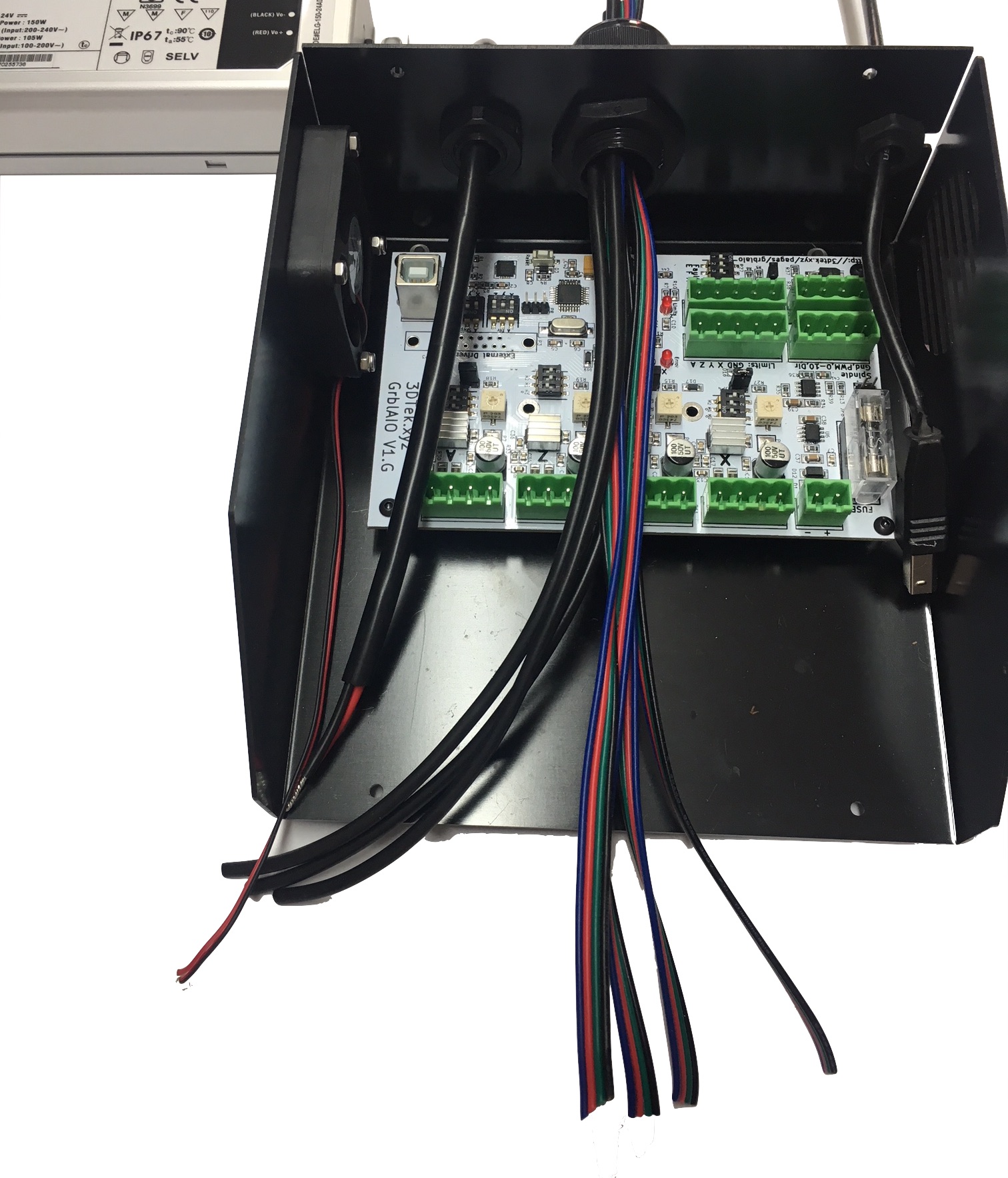
Identifying GRBL AIO Components.
Main.
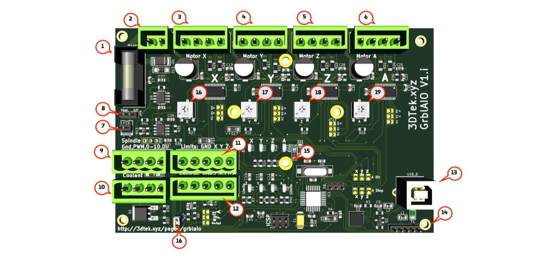
Click image to enlarge.
- Fuse - 5x20mm - Suggested 7 to 10 A 5mm Diameter x 20mm Length. This fuse acts on the 12-36V motor power circuit.
- 12-36V DC power in.
- X Motor output
- Y Motor output
- Z Motor output
- A Motor output
- Fan Connector.
- Fan Voltage selector
- Spindle control output - unused on XYZ Carve
- Coolant Control - not used
- Limit Switch Inputs, - The A limit pin is unused.
- CNC Control (Probe / Resume /Feed Hold / Estop)
- USB IO - you guessed it, stick the USB cable in here.
- Alt UART Connector - Not used
- Fan Mounting Screw Hole Pattern - Not used
- X Current Limiting Pot
- Y Current Limiting Pot
- Z Current Limiting Pot
- A Current Limiting Pot
Jumpers.
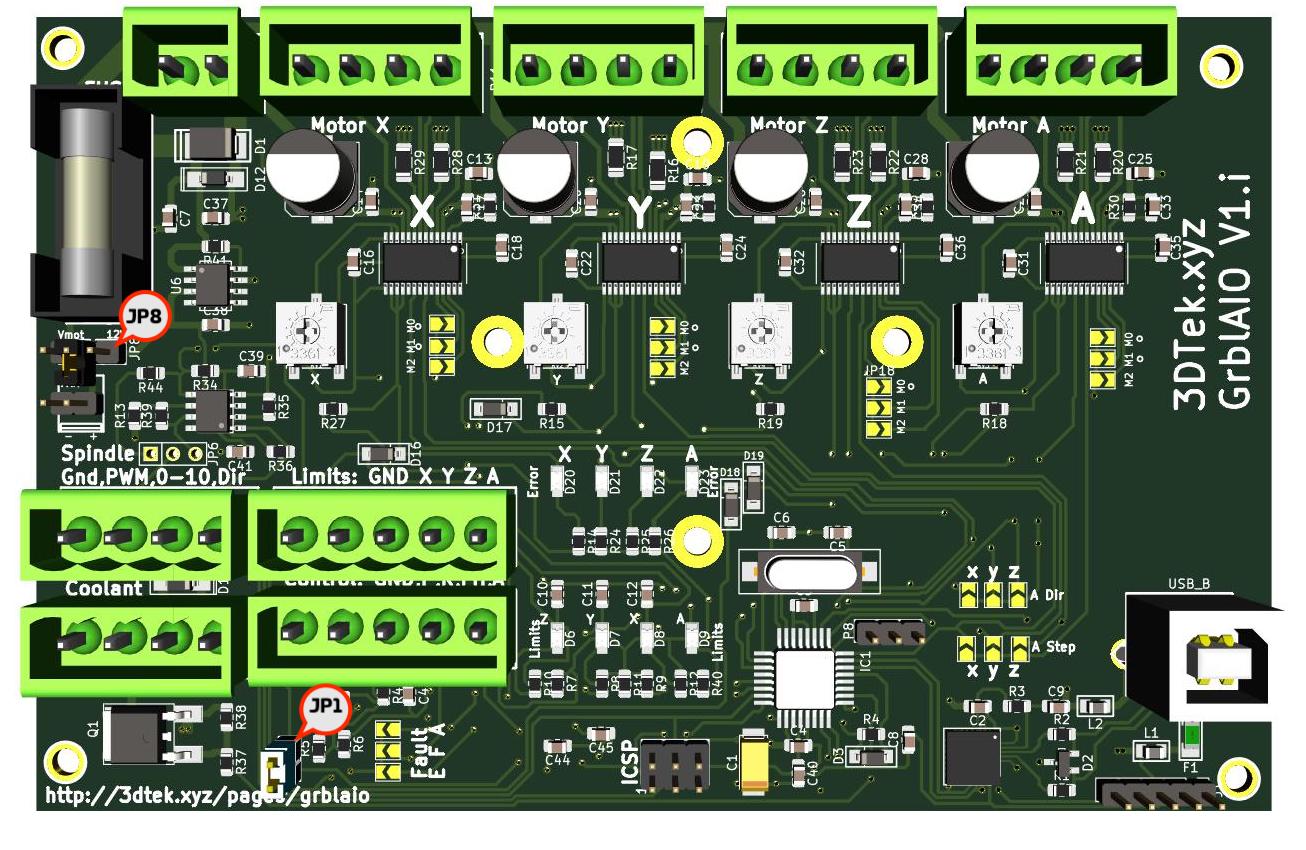
Click image to enlarge.
- JP8 - Fan power, Jumper across centre and 12V pin when using a 12V fan, across centre and Vmot for fans with save voltage as power supply used (24v). Note fan voltage generally printed on sticker
- JP1 - Removed only while in programming VIA ICSP
Driver current setting pots
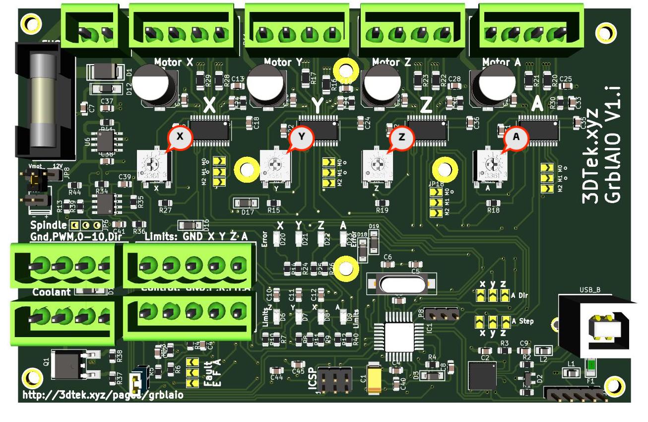
Click image to enlarge.
- X. X Driver current limiting trim pot
- Y. Y Driver current limiting trim pot
- Z. Z Driver current limiting trim pot
- A. A Driver current limiting trim pot
These pots reduce current output of drivers when turned clockwise. Initially set all the way clockwise then a 1/4 turn anticlockwise. Be gentle with these pots.
Step 1: Attach AIO Card to enclosure
Using 4 small m3 BHCS provided, install AIO card into inclosure oriented as per the photo.
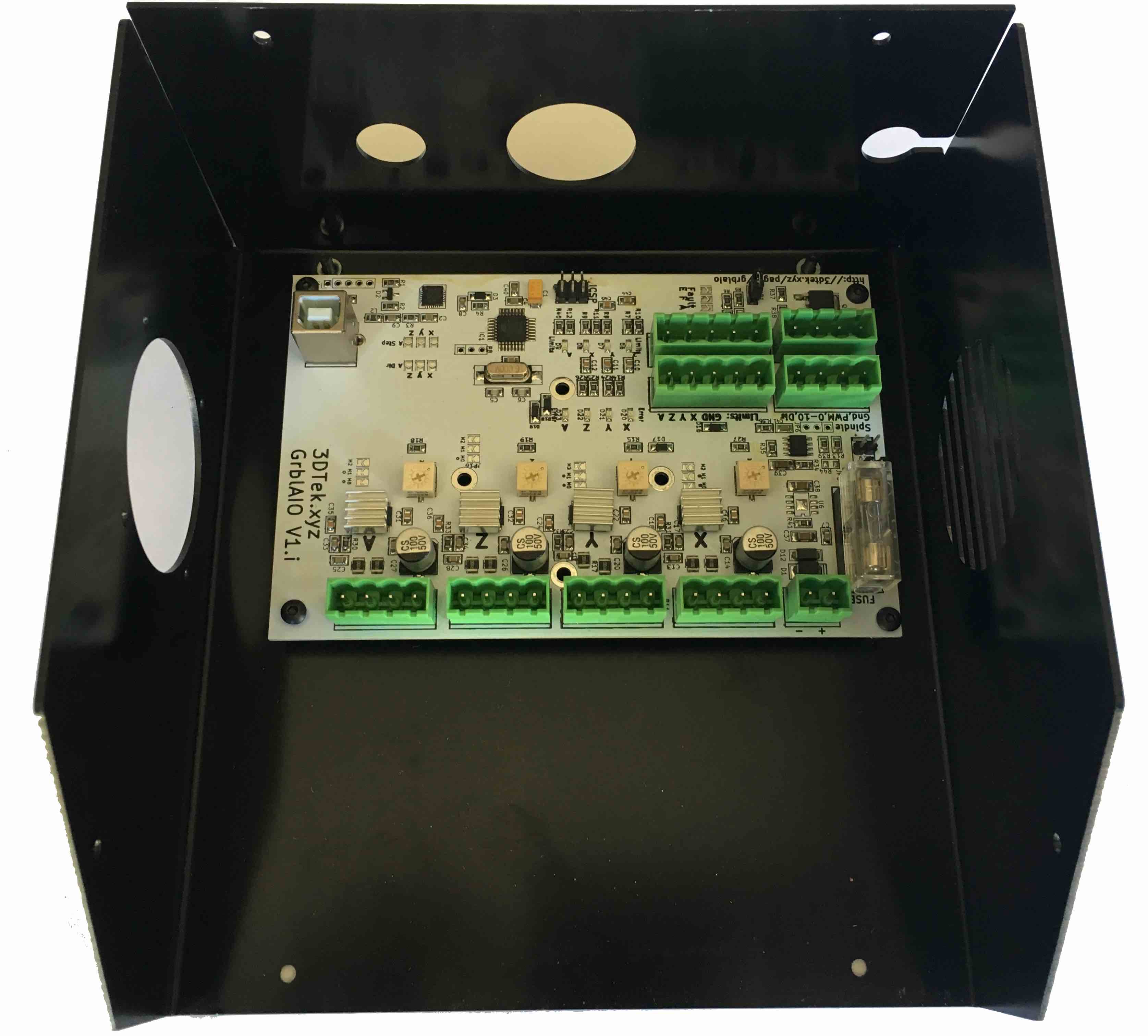
Click image to enlarge.
Step 2: Preset Current Limiting Resistors
There are four variable resistors / trim pots. One for each driver
Dial each clockwise all the way, careful they only turn 270 degrees, then turn back anti clockwise 1/8 of a turn only (5 minutes on a clock face). This is a good starting point. When tuning the machine at a later point you may need to adjust these anticlockwise for some more power or clockwise if the motors are getting hot. YOU MUST turn these screws on top of the potentiometer all the way clockwise then back only 1/8 of a turn, or 5 mins on a clock face. Keep an eye on the stepper motor temperatures, they should be warm not hot. If any motor is too hot turn its associated trim pot a little bit clockwise, wait a few minutes and check the temperature again. It takes a few minutes for temperatures to stabilise after adjustment. Click image to enlarge.
Step 3: Bring Wires into enclosure
All wiring enters the rear of the enclosure through one of three cable glands
- Power Supply through rear left PG9 gland
- All Stepper & Limit Switch Cables through large centre gland.
- USB through rear right gland - note PG7 gland already installed on the USB lead.
Trim all wires (other than USB!) to around 20cm in length from entry into the enclosure.
Keep some of the limit switch or stepper wire offcuts for next steps.
Click image to enlarge.
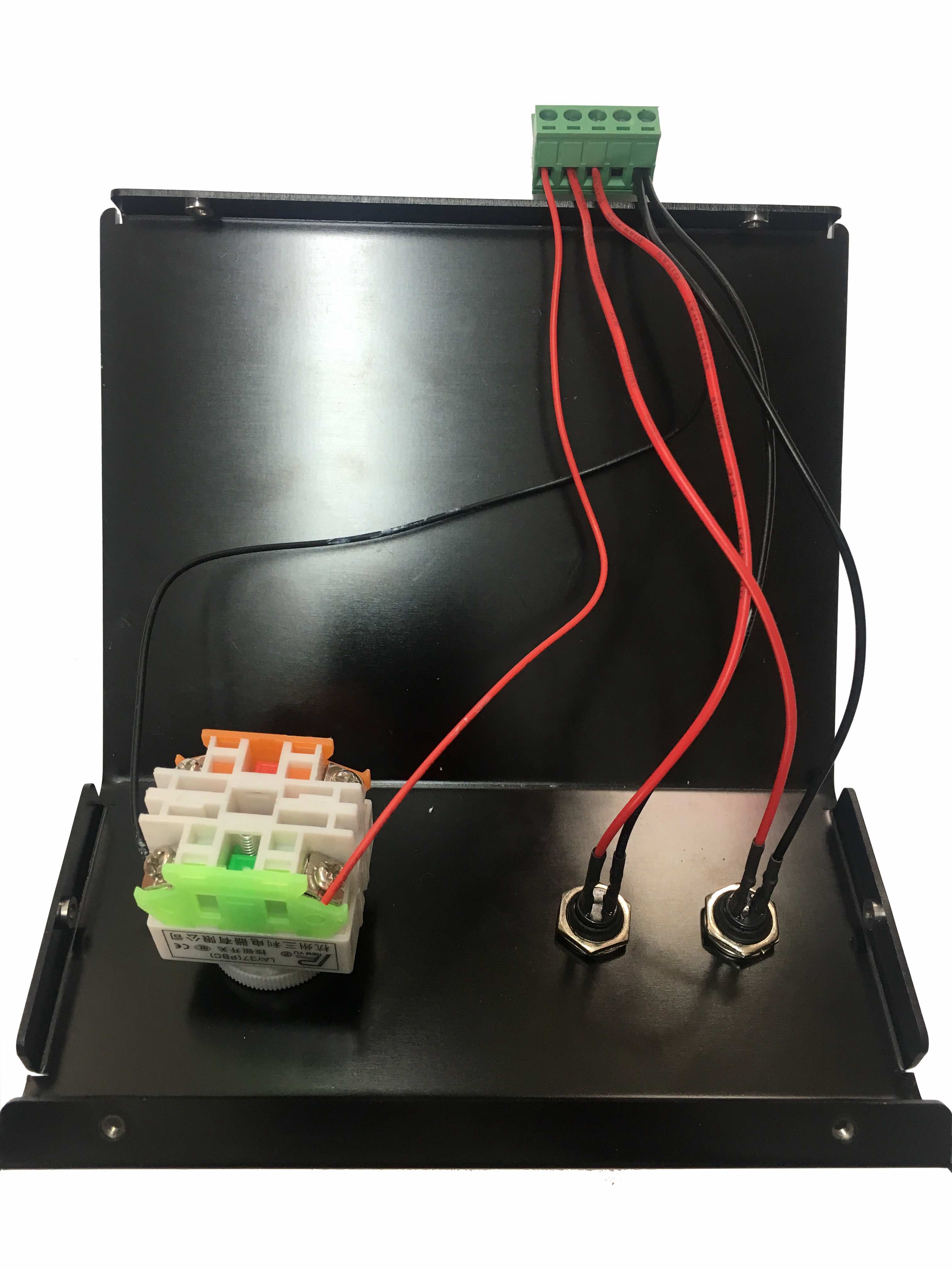
Step 4: Terminate Estop, Feed Hold and Resume Circuits
The estop has two circuits. The Green side is normally open, the orange normally closed. We will use the NO configuration for all our switches (Estop, Feed Hold, Resume & and Limits)
Take two pieces of off-cut wire, black and red is good, terminate one into each side of the green circuit on the limit switch.
Take the black wire just inserted into the estop switch, combine it with the two black wires from the green and yellow Feed Hold and Resume switches, and insert them into pin five of one of the 5 pin green plugs.
Take the red wire from the green switch and terminate into pin three
Take the red wire from the yellow switch and terminate into pin two
Take the red wire from the Estop switch and terminate into pin one

Step 4: Identify, Terminate Limit Switches.
You will have 3 sets of 2 core cables that you have already connected to your limit switches
If you have not already labeled them with X Y & Z you will need to trace the wires back or use a multimeter to identify which wires are for which switch. It can be done later during the software setup if your not able to do so now.
- Bare back the insulation on the limit switch wires. Select one of the two wires from each switch, twist them together and terminate into pin 1 of the remaining 1 pin plug.
- Terminate the remaining wire from the X limit switch into green plug pin 2
- Terminate the remaining wire from the Y limit switch into green plug pin 3
- Terminate the remaining wire from the Z limit switch into green plug pin 4
- Pin 5 remains unconnected
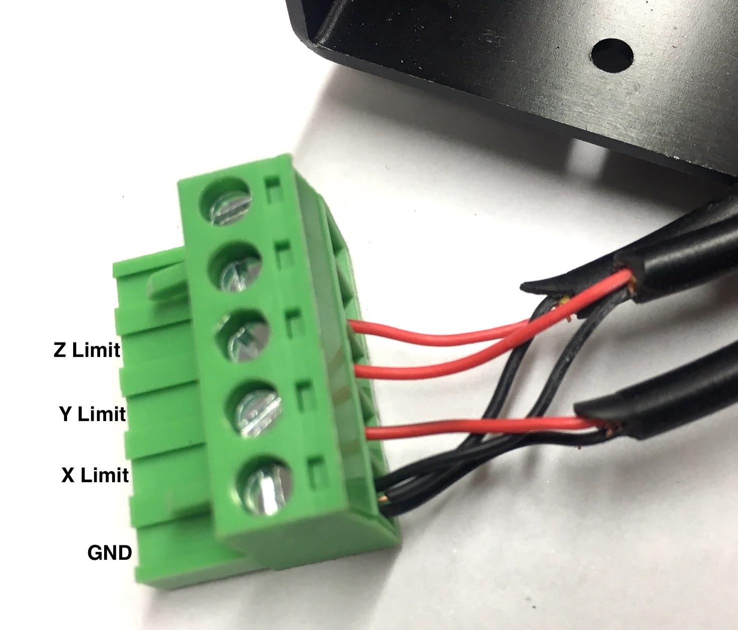
Click image to enlarge.
Step 6: Identify, Terminate and Label Stepper Motor Circuits
You will have 4 of sets stepper wires coming into your enclosure
Each Stepper has two pairs, these are generally Black + Green as pair one and Red + Blue as pair two, however due to availability, occasionally yellow or white is used instead of blue.
If you have not labeled each stepper motor yet, follow these steps for each motor, one at a time
- Strip the insulation back on each wire so that approx 10mm of copper is showing
- Twist together the green and black wires

Click image to enlarge. - Making sure that no other wires are touching, attempt to move each axis of the machine and take notice which one seems to have more resistance when the green black wires are connected. The motor that is hard(er) to move corresponds to the set of wires that you have shorted green black.
- Label this motor now, X direction is left right, Y direction is front back, Z direction is up down.
- There are two Y motors on your gantry, one on each side. - one of these motors will be known going further as Y and the other A - does not matter which is which.
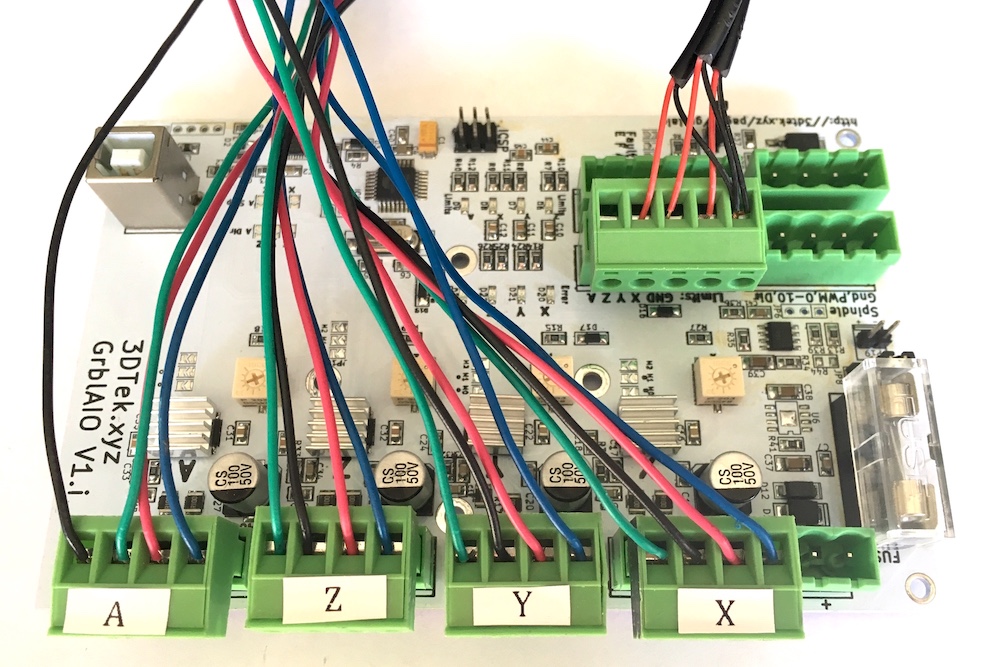
Now that each motor is identified, terminate each motor into its own green plug following the wiring colours shown below.
Remember not to get insulation stuck inside the terminal, and not to leave copper hanging out of the terminal where it might short out with another wire.
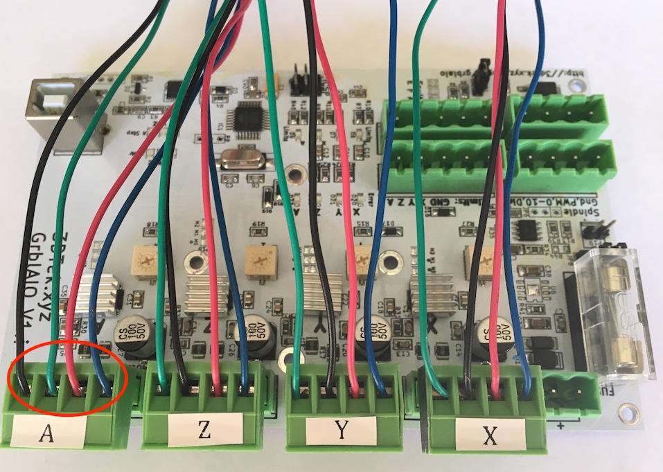
Click image to enlarge.
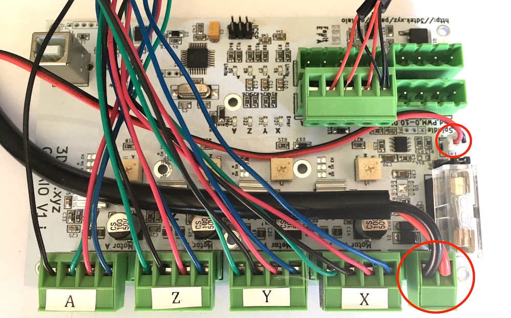
Step 7: Terminate Power Supply
Connect the power supply wires to the 2 pin green plug as shown below.
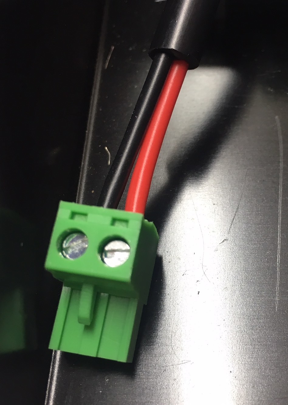
Click image to enlarge.
Its very important that the polarity is correct here!
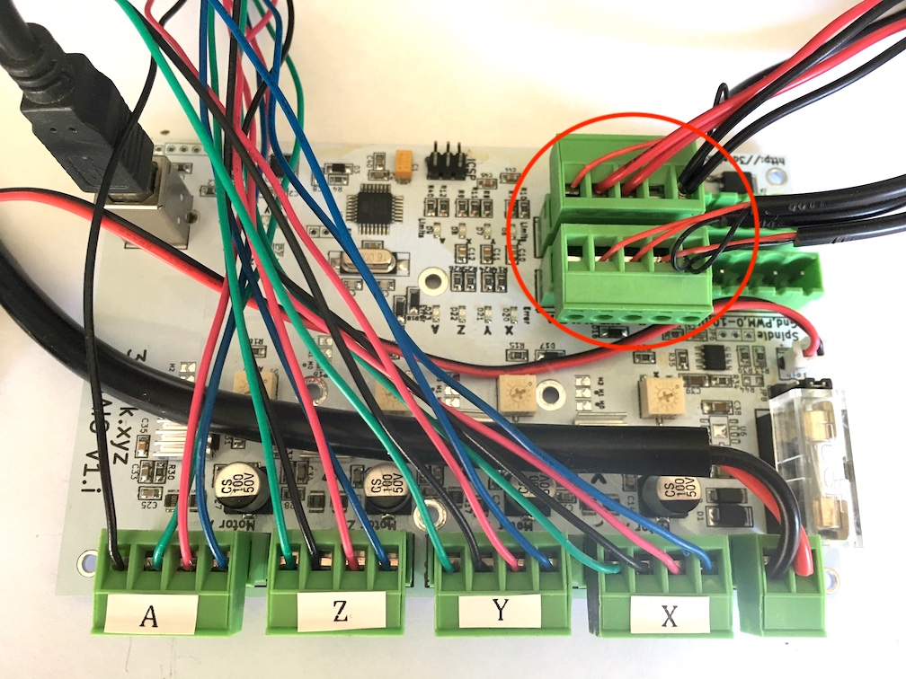
Step 8: Connect all plugs to AIO
Plug 5 pin limit switch plug into the aio in the position shown below

Click image to enlarge.
Plug In all four stepper 4 pin plugs, in the order shown below.
Click to enlarge
Plug in Power and Fan plugs as shown below. Some fans, 24V fans only, are instead supplied without white plugs on the end, in which case they can be wired directly in with the 24V power supply into the 2 pin green plug.
Click to enlarge
Plug in USB Cable

Click to enlarge
Plug in Front Panel Switch Plug
Click to enlarge You may now replace the enclosure cover. </div>
<=Enclosure. Software Setup=>