
<=Install Gantry. Belts=>
Drag Chain and Wiring.
Notes Before you start:
- It's highly advisable to label both ends of each motor and switch cable as you install them to save trying to identify them at the control box end once they are run through the drag chain and can no longer be seen
- Do not cut short any of the motor wiring, keep as much length available until setting up the control box at which point all wires can be cut to the same length.
- Included in the kit are two sizes of expanding cable braid. It can be used, for aesthetics, at any point where wires are exposed. It's difficult to work with and frays readily without tape or heat shrink around the ends, however makes for a tidy looking machine if utilised. The smaller braid is good for single limit switch or motor wires and the thicker piece will enclose the entire wiring harness from the point it leaves the base of the Y drag chain until it enters the control box.
- Router wiring can be included in the drag chain, cable tied to the outside of the drag chain or more commonly lowered/dangled from a position above the machine.
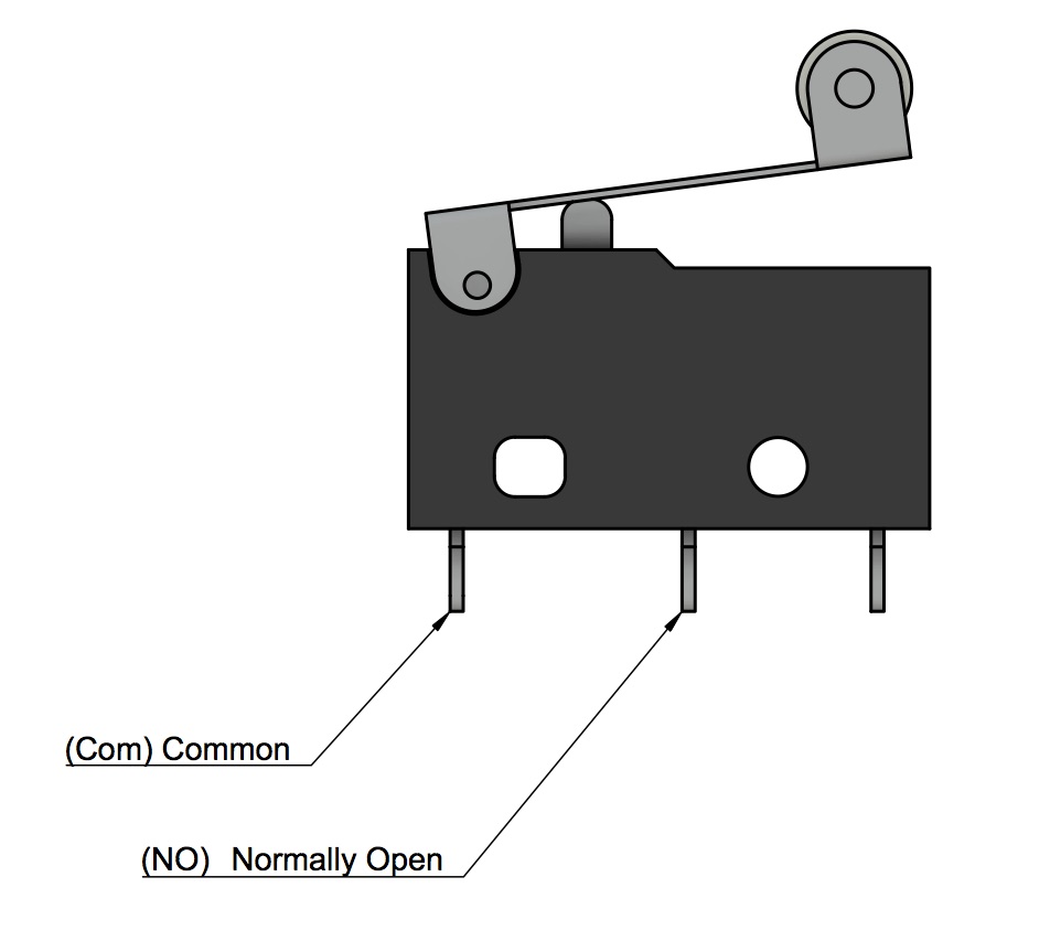
- Wiring the limit switch is in normally open (NO) configuration. This uses pins marked COM and NO which are the pin under the lever hinge and the center pin.
It's not important which pin is which at the control box end but choose one colour to connect to the COM and use that same colour on the COM for each switch.
- The wiring can be fed through the drag chain using a draw wire, or alternatively the underside of the drag chain links are removable.
- Do not tape or cable tie wires together as they will become difficult to route through the drag chain.
- The steppers are custom made with five meters of stepper motor cabling or are supplied with plug in extension fly leads and so no soldering is required.
- The A motor (right hand side of the gantry, opposite side from Y drag chain, will need its wires run through the X axis Maker Slide if not already done, It will meet up with the Y drag chain and continue through to the front of the machine.
- Routing the wires is fairly straight forward. As mentioned the 4 core cable can be used for the limit switch wires and all Steppers have their own wiring. Each cable enters the closest section of drag chain and exits the machine at the base of the Y drag chain. Cables leaving the X Drag Chain all link into the Y drag chain.
Best viewed in full screen using the
 button at the right of the bottom toolbar.
Wiring can be completed in the following steps.
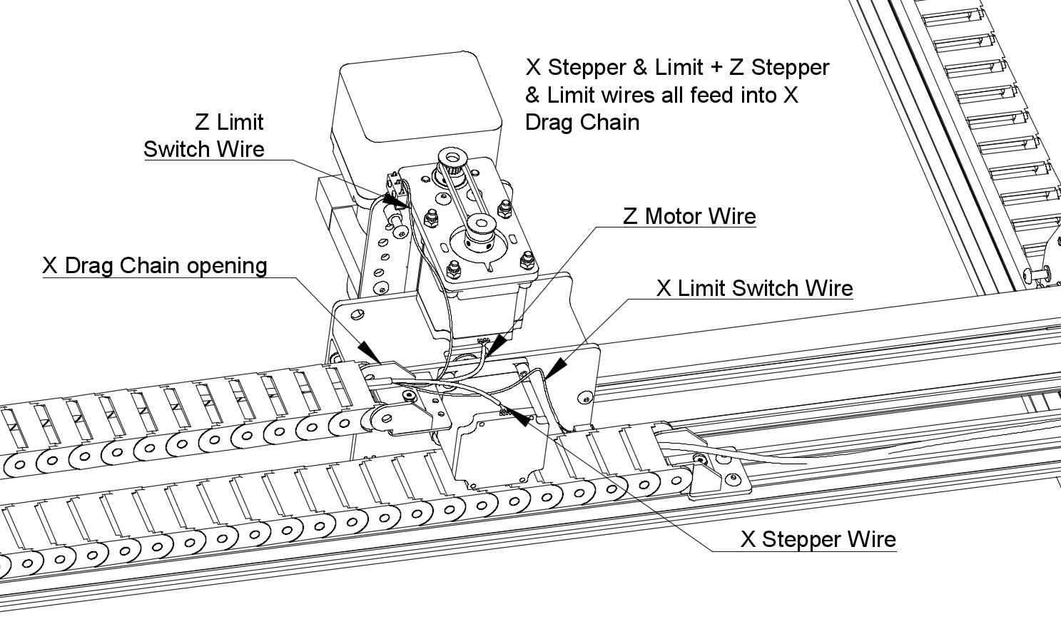
Step 1: X & Z Stepper & Limit Switch Wiring
- 4 cores of wire, (X motor, Z motor, X Limit Switch, Z Limit switch), all begin in the region shown below, the back of the X Carriage.
- A small section of braid, enough to go from the switch or motor connection to the drag chain can be slipped onto each wire at this point if you elect to use the braid. Melting the ends slightly stops the braid fraying. Bunching the braid together makes it expand, and stretching it makes it contract. A small piece of heat shrink covers the ends and stop it from fraying as well as adding to tidiness.
- Z Limit Switch: Cut the supplied limit switch cables in to 3 pieces of equal length. Using one of the three connect its wires to each of the two pins ( marked Com & NO) as shown below. Leaving the third pin marked Marked NC unconnected.
- X Limit Switch: Repeat same for X Limit Switch.
- If you were supplied extension wires for the Stepper motors, connect them now to the X & Z stepper motors
- Run all 4 wires ( X & Y Limits and motors) through the X axis Drag Chain. Methods for doing this include
- Removing underside of each drag chain link, running cable through and replacing removed pieces. These will release easily without any tools and snap back into place readily.
- feeding a single draw wire through the chain, taping your 4 wires to this and pulling the draw wire through to drag others behind it.
Step 2: A Stepper Motor Wiring
- The A stepper motor is the stepper motor mounted on the Y Gantry plate that is on the opposite side of the machine from where you have installed the Y drag chain. Connect a stepper extension wire to it if you were supplied one, otherwise, the motor wire will already be approximately 5 meters.
- Route the A stepper motor wire through the slotted hole in the gantry plate (directly above the drag chain support bracket), Gantry plate, through the X Axis wide makerslide, and out of the same hole in the Y gantry plate at the opposite end of the gantry as shown below. (Ideally you have done this already, or are just skipping ahead from the gantry step 6)
Best viewed in full screen using the button at the right of the bottom toolbar.
Step 3: Y Stepper & Limit Switch Wiring
- The Y stepper motor is the stepper motor mounted on the Y Gantry plate that closest to the Y drag chain. Connect a stepper extension wire to it if you were supplied one, otherwise the motor wire will already be approximately 5 meters.
- Y Limit Switch: Using the last of the the three supplied 2 core limit switch cables connect one wire to each of the two pins (Com & NO) as shown below. Leaving the third pin marked Marked NC unconnected.
Best viewed in full screen using the button at the right of the bottom toolbar.
Step 4: Y Drag Chain
- Sections of the small and large braid can be used here to cover any wires that will be external to drag chain.
- Gather up all of the wires, secure the bunch of tails with electrical tape and feed all through the Y drag chain. Consider again using a draw wire or removing all of the underside sections of the drag chain links.
- Once all wires are through, remove electrical tape binding the tail together and pull wires individually to desired length / tension.
- Some cable ties can be applied to the small amount of exposed wiring running along the drag chain support between the end of the x drag chain and the end of the X axis
Machine Wiring Complete:
All required wiring should now be exiting the Y drag chain at the machines front left.Further wiring into the electronics enclosure is covered in future steps.
The only other wiring component is the routers power lead, which can be:
- Dangled from above.
- Cable tied or otherwise secured to the outside of the X Drag chain.
- or otherwise secured in your preferred fashion. NOTE:The Router cable should not be left to float around the waste board or be routed in any way that the machine is able to cut, pinch or otherwise damage it during operation - this could be life threatening.
<=Install Gantry. Belts=>