
<=X Carriage Y Rails=>
Z Axis.
How to view the animation?
Best viewed in full screen using the button at the right of the bottom toolbar.
Best viewed in full screen using the button at the right of the bottom toolbar.
Best viewed in full screen using the button at the right of the bottom toolbar.
Best viewed in full screen using the
button at the right of the bottom toolbar.
Best viewed in full screen using the
button at the right of the bottom toolbar.
Best viewed in full screen using the
button at the right of the bottom toolbar.
Notes Before you start:
- The Z Acme Lower Plate has a tight fit with its Flanged Bearing. Powder coating thickness tolerances can make this even tighter. You may need to rub the inside of this hole with some sandpaper to be able to insert the bearing. It may take some soft tapping with a hammer to insert - if so place a small piece of timber between the bearing and the hammer to soften and spread the impact.
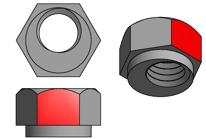
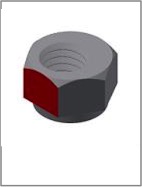
- The M5 threaded hole in the eccentric nuts is offset from centre. It's helpful to mark the closest side with a marker, shown below in red, as it's difficult to identify the short side once installed.
- Install the eccentric nuts into the spindle carriage plate (which you have marked) facing the side of the plate that has both eccentric nuts.
Z Axis BOM:
|
|
|||
| Qty | Part | Image | |
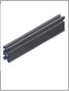
| 1 | Makerslide Z Axis 200mm |
 |
|
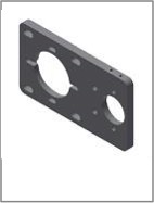
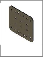
| 1 | Z Motor Plate |
 |
|
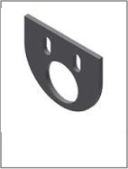
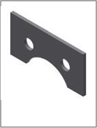
| 1 | Z Acme Lower Plate |
 |
|
| 1 | Z Acme Plastic Shim |
 |
|
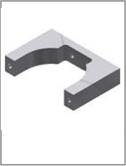
| 1 | Spindle Mount Plate |
 |
|
| 1 | 65mm or 69mm Spindle Mount Front (Optional) |
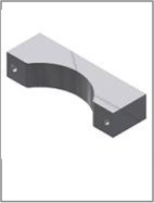 |
|
| 1 | 65mm or 69mm Spindle Mount Back (Optional) |
 |
|
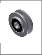
| 4 | Dual Bearing V Wheel |
 |
|
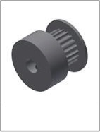
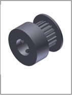
| 1 | GT2 Pulley 1/4 in Bore |
 |
|
| 1 | GT2 Pulley 8mm Bore |
 |
|
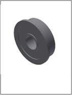
| 2 | F608-2RS Flanged Bearing |
 |
|
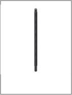
| 1 | Z Acme Thread 232mm |
 |
|
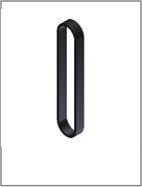
| 1 | GT2 Closed Loop Belt 80 Tooth |
 |
|
| 1 | Z Acme Lead Nut Block |
 |
|
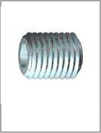
| 4 | Grub Screw- M3x0.5 x 5 (Installed In Pulleys) |
 |
|
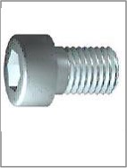
| 4 | Socket Head Cap Screw - M5x0.8 x 20 |
 |
|
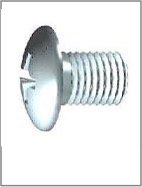
| 2 | Pan Head Machine Screw - M2x0.4 x 10 |
 |
|
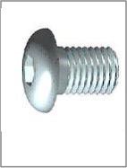
| 2 | Socket Button Head Cap Screw - M5 x 0.8 x 8 |
 |
|
| 4 | Socket Button Head Cap Screw - M5 x 0.8 x 12 |
 |
|
| 4 | Socket Button Head Cap Screw - M5 x 0.8 x 16 |
 |
|
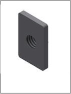
| 3 | Tee Nuts Mix of Pre and Post Assembly |
 |
|
| 4 | Socket or Button Head Cap Screw - M5 x 0.8 x 35 to 40mm |
 |
|
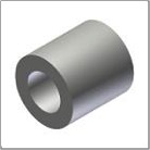
| 4 | Spacer |
 |
|
| 2 | Eccentric Nut |
 |
|
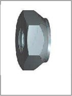
| 6 | Prevailing Torque Hex Nut - M5 x 0.8 |
 |
|
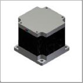
| 1 | Nema 23 Stepper |
 |
|
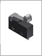
| 1 | Limit Switch (3 required, 1 spare) |
 |
|
| 1 | Makita_RT0700X |
 |
|
<=X Carriage Y Rails=>