
<=Gantry Side Plates Z Axis=>
X Carriage.
How to view the animation?
Best viewed in full screen using the button at the right of the bottom toolbar.
Best viewed in full screen using the button at the right of the bottom toolbar.
Best viewed in full screen using the
button at the right of the bottom toolbar.
Best viewed in full screen using the
button at the right of the bottom toolbar.
Notes Before you start:
- The drag chain end links are shown as a part separate from the drag chain, you will find them however already connected to the ends of the drag chain. You may remove the end link and install it as shown here, or leave it on the chain and install as once piece at a later point.
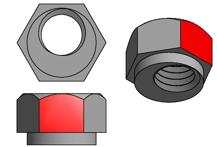
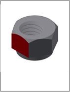
- The M5 threaded hole in the eccentric nuts is offset from centre. It's helpful to mark the closest side with a marker, shown below in red, as it's difficult to identify the short side once installed.
- Install the eccentric nuts into the X Carriage with the shortest side (which you have marked) facing the bottom of the X Carriage
- Hardware
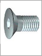
- The two idler wheels are secured with Flat Head Socket Cap Screws M5 x 0.8 x 35.
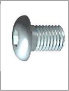
- V Wheels are secured with Socket Button Head Cap Screw M5 x 0.8 x 25
- Stepper motor is secured with Socket Head Cap Screw - M5x0.8 x 10
X Carriage BOM:
|
|
|||
| Qty | Part | Image | |
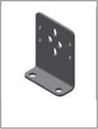
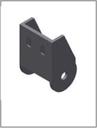
| 1 | Drag Chain Support Bracket 1 |
 |
|
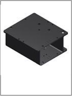
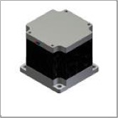
| 1 | Extruded X Carriage |
 |
|
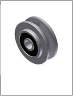
| 8 | Dual Bearing V Wheel |
 |
|
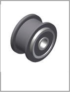
| 2 | Dual Bearing Idler Pulley |
 |
|
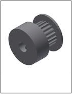
| 1 | GT2 Pulley 1/4 in Bore |
 |
|
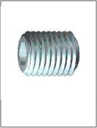
| 2 | Grub Screw- M3x0.5 x 5 (Installed In Pulleys) |
 |
|
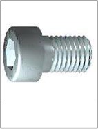
| 4 | Socket Head Cap Screw - M5x0.8 x 10 |
 |
|
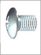
| 2 | Pan Head Machine Screw - M2x0.4 x 14-16 |
 |
|
| 2 | Socket Button Head Cap Screw - M4 x 0.7 x 10 |
 |
|
| 2 | Socket Flat Countersunk Head Cap Screws - M5x35 |
 |
|
| 2 | Socket Flat Countersunk Head Cap Screws - M4x10 |
 |
|
| 8 | Socket Button Head Cap Screw - M5 x 0.8 x 25 |
 |
|
| 2 | M2 Nylock Nut |
 |
|
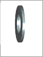
| 8 | M5 Washer |
 |
|
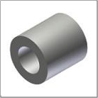
| 2 | Spacer |
 |
|
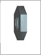
| 4 | Eccentric Nut |
 |
|
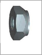
| 4 | Prevailing Torque Hex Nut - M4 x 0.7 |
 |
|
| 6 | Prevailing Torque Hex Nut - M5 x 0.8 |
 |
|
| 1 | Nema 23 Stepper |
 |
|
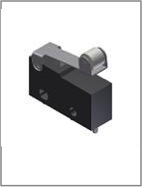
| 1 | Limit Switch (3 required, 1 spare) |
 |
|
| 1 | Drag Chain Ends (supplied installed on drag chain) |
 |
|
<=Gantry Side Plates Z Axis=>