
<=BOM X Carriage=>
Gantry Side Plates.
Best viewed in full screen using the
 button at the right of the bottom toolbar.
Notes Before you start:
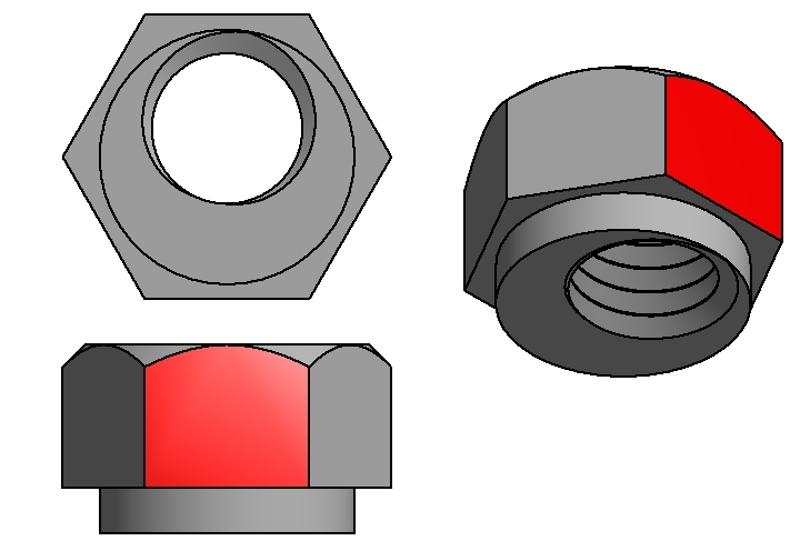
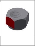
- The M5 threaded hole in the eccentric nuts is offset from centre. It's helpful to mark the closest side with a marker, shown below in red, as it's difficult to identify the short side once installed.
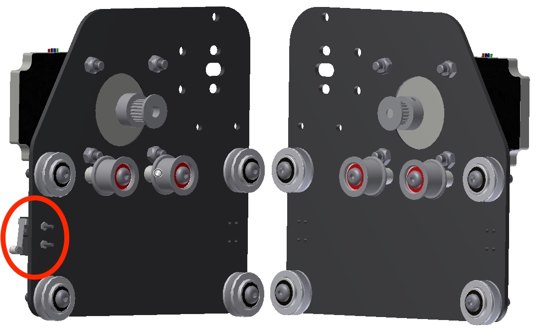
- Install the eccentric nuts into the end plates with the shortest side (which you have marked) facing the bottom of the Gantry End Plate
- The limit switch goes on the front side of the left Gantry End Plate only (as circled below) otherwise, the left and right sides are simply images of each other.
- The Limits switch secures with an m2x14mm screw and nylock nut. These are rare and hard to find. Occasionally the market can only supply m2x16mm and so if your supplied screws are 2mm longer (16mm) then they must be inserted from the V wheel side of the gantry side plate with the nut on the outside/switch side, opposite to that shown in the video and cad images.
- Hardware
- Idler wheels are secured with Socket Button Head Cap Screw M5 x 0.8 x 35.
- V Wheels are secured with Socket Button Head Cap Screw M5 x 0.8 x 25
- Stepper motors are secured with Socket Head Cap Screw - M5x0.8 x 16
- Remember to make two! Mirror images of each other.
- The GT2 Pulleys should be fastened in a position on the motor shaft where they line up with the Idler wheels once installed.
Gantry Side Plates BOM (qty each side plate):
| Qty | Part | Image |
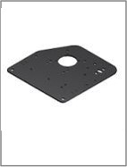
| 1 | Gantry Side Plate |
 |
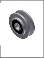
| 4 | Dual Bearing V Wheel |
 |
| 2 | Dual Bearing Idler Pulley |
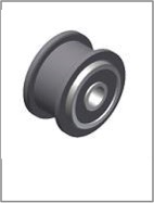 |
| 1 | GT2 Pulley 1/4 in Bore |
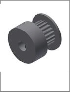 |
| 2 | Grub Screw- M3x0.5 x 5 (Installed In Pulleys) |
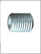 |
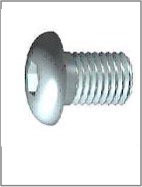
| 4 | Socket Head Cap Screw - M5x0.8 x 16 |
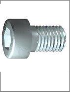 |
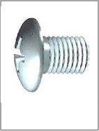
| 1 | Pan Head Machine Screw - M2x0.4 x 14-16 |
 |
| 2 | Socket Button Head Cap Screw - M5 x 0.8 x 35 |
 |
| 4 | Socket Button Head Cap Screw - M5 x 0.8 x 25 |
 |
| 1 | M2 Nylock Nut |
 |
| 4 | M5 Washer |
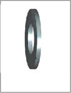 |
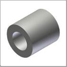
| 2 | Spacer |
 |
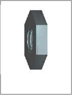
| 2 | Eccentric Nut |
 |
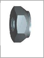
| 8 | Prevailing Torque Hex Nut - M5 x 0.8 |
 |
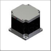
| 1 | Nema 23 Stepper |
 |
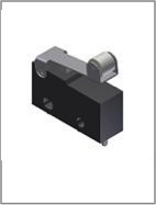
| 1 | Limit Switch |
 |
<=BOM X Carriage=>